Power control boards built around your source, load and safety requirements.
Inverter, power distribution, solar conversion, wireless charging and storage boards share a need for clear electrical boundaries, but they do not share one interchangeable design. Begin with the energy source, loads, interfaces and fault behavior. Then identify which board or subassembly is required and what the complete product must do.
Browse product boards and subassemblies from the existing page catalogue. Product images are category references; the approved drawing, BOM, configuration and acceptance criteria define each customer build.
01 / PRODUCT FAMILY
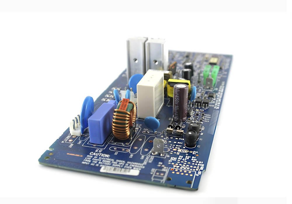
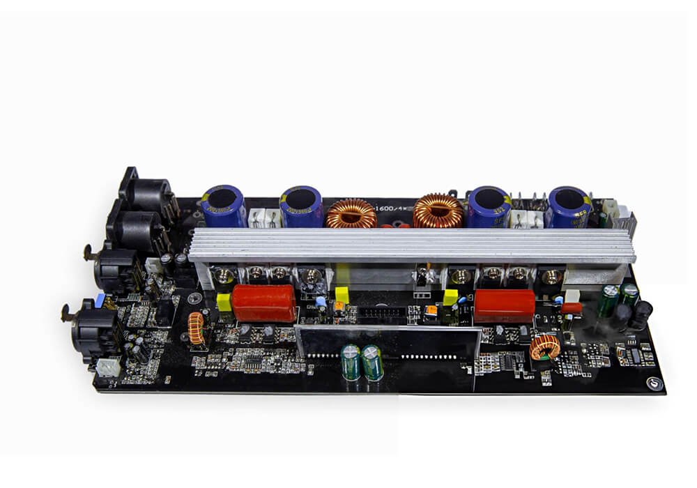
Inverter PCB
An inverter board is part of a system that converts or controls electrical power. For an enquiry, identify the source, output, operating modes, load changes and the external parts the board must connect to. Layout, heat removal, switching behavior and test access all depend on that system context.
Inverter PCB
Inverter Power Stage PCB
Inverter Control PCB
02 / PRODUCT FAMILY
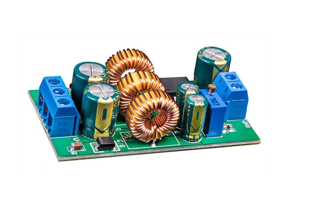
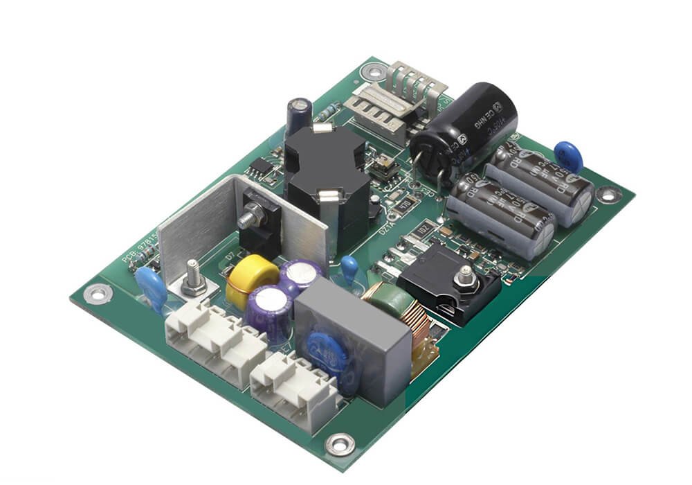
Power PCB
A general power PCB can distribute, condition or convert energy inside an electronic product. Specify the expected current paths, power stages, connectors, cooling method and available installation space. The resulting board construction and assembly checks should follow the agreed electrical and physical requirements, rather than a generic board label.
Power PCB
Power Distribution PCB
Regulated Power PCB
03 / PRODUCT FAMILY
Solar Inverter PCB
A solar inverter board brings photovoltaic input conditions, control functions and power conversion into one project discussion. Provide the intended input and output ranges, installation environment and the role of the board in the complete inverter. Safety, environmental and market requirements need to be assigned to the correct product and responsible party during scoping.
Solar Inverter PCB
Solar Inverter Input PCB
Solar Inverter Control PCB
04 / PRODUCT FAMILY
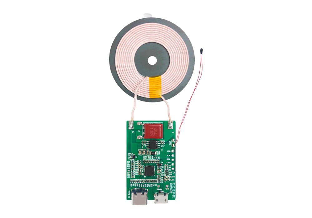
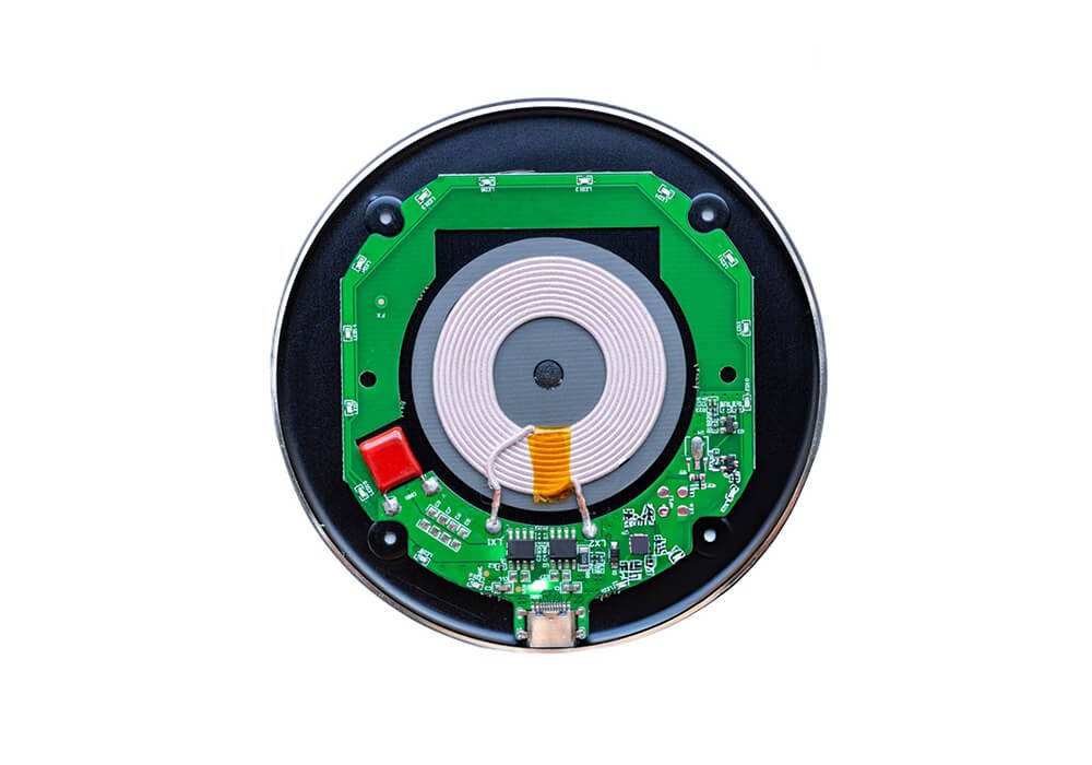
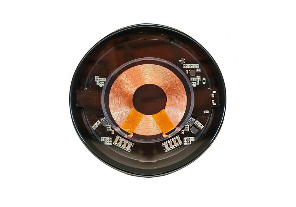
Wireless Charger PCB
A wireless charging board has to work with its coil, power input, receiver relationship, housing and user positioning. The project brief should describe charging power, device alignment, available space, heat dissipation and the intended use. Any interoperability or certification target must be identified as a project requirement, not assumed from the board image.
Wireless Charger PCB
Wireless Charging Control PCB
Wireless Charger Interface PCB
05 / PRODUCT FAMILY
Energy Storage PCB
An energy storage application may involve control, monitoring or power transfer boards around a battery system. The board’s role, battery interface, operating conditions and fault responses must be defined before a design or manufacturing scope can be agreed. A PCB photograph alone cannot establish the safety responsibilities of the finished storage product.
Energy Storage PCB
Energy Storage Monitoring PCB
Energy Storage Power PCB
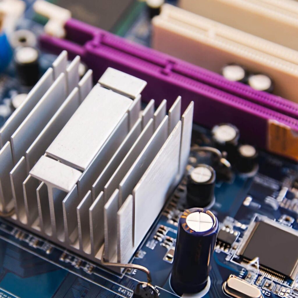
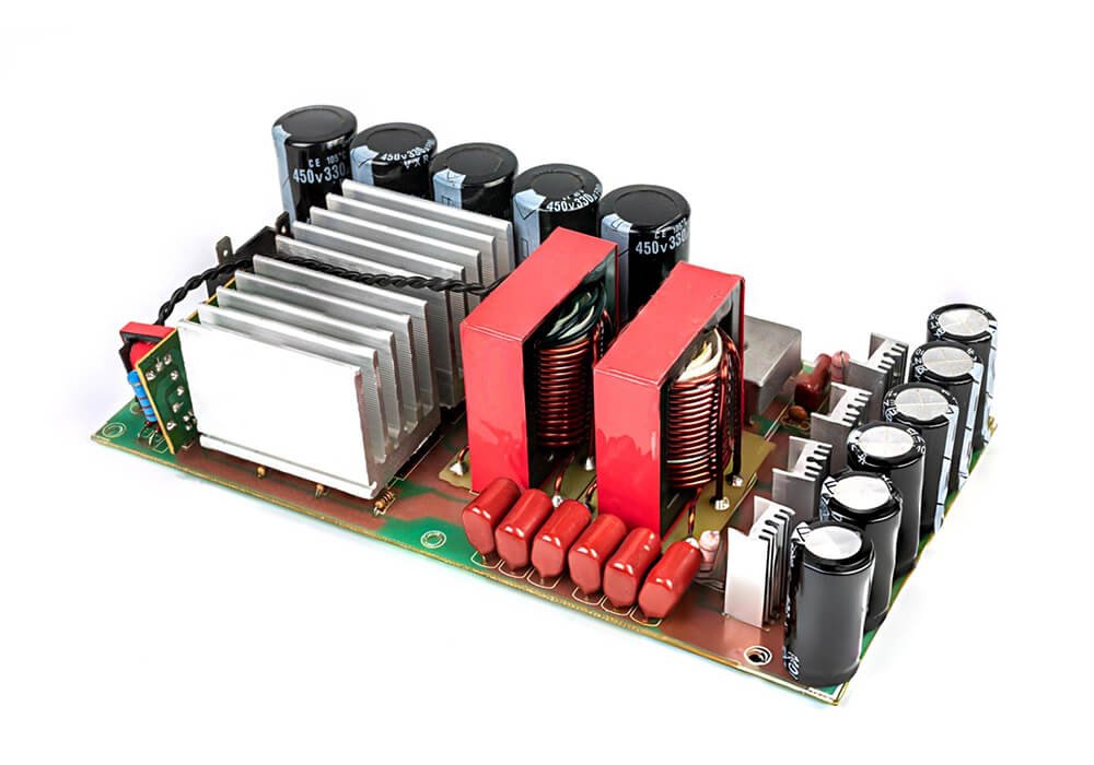
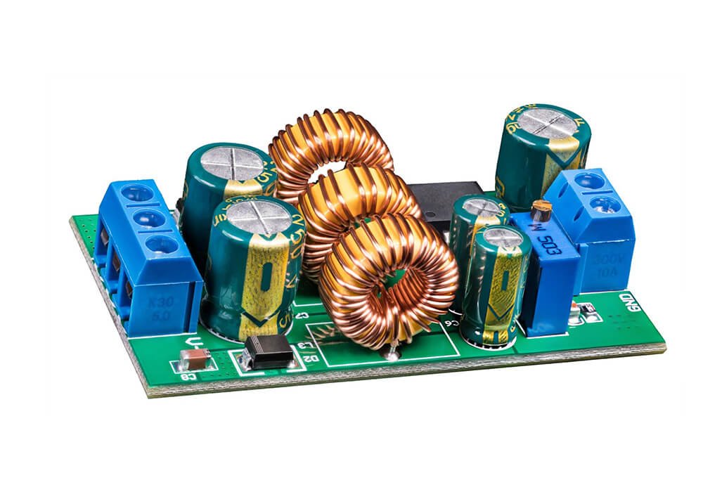
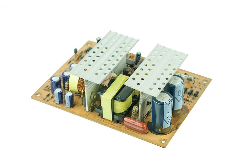
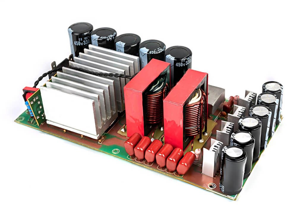
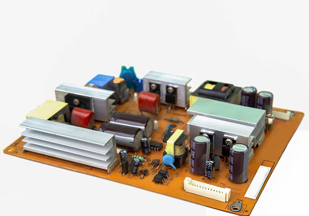
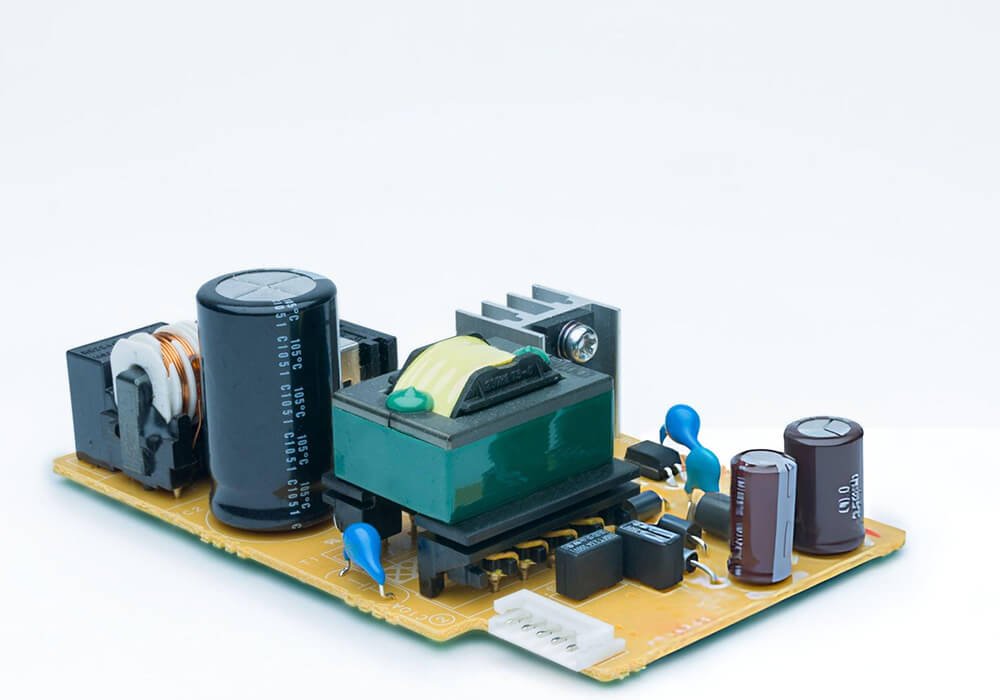
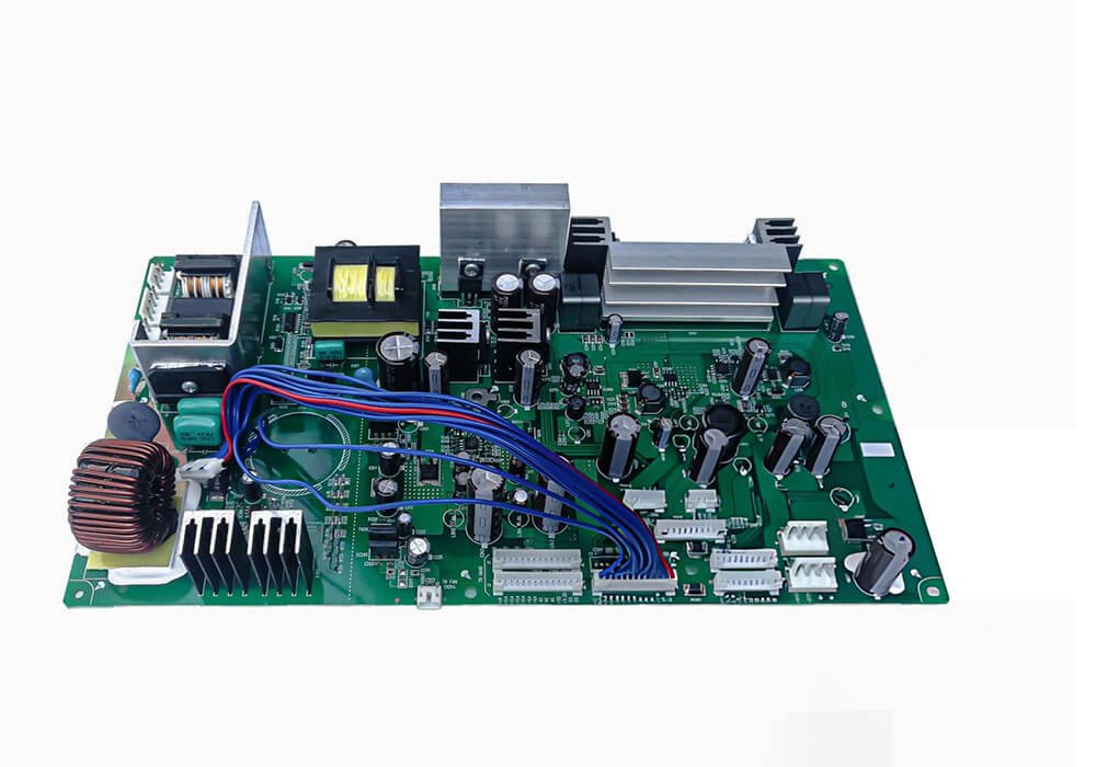
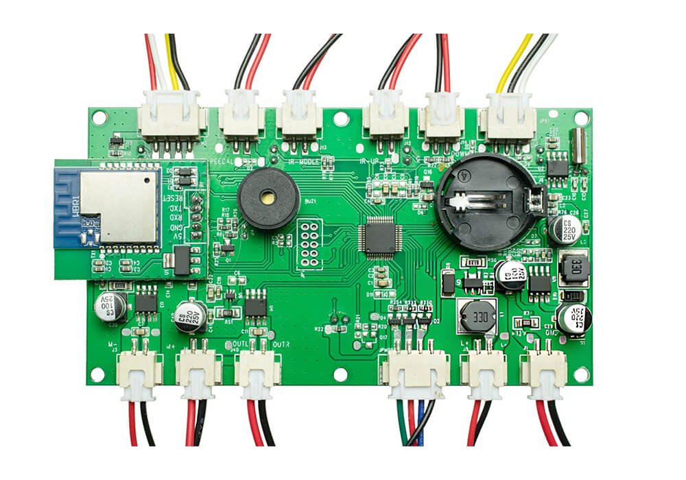
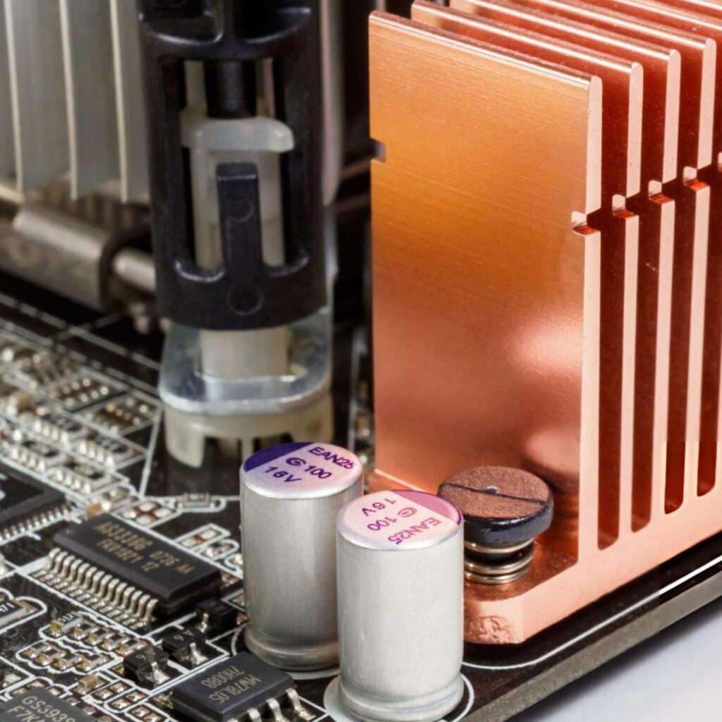
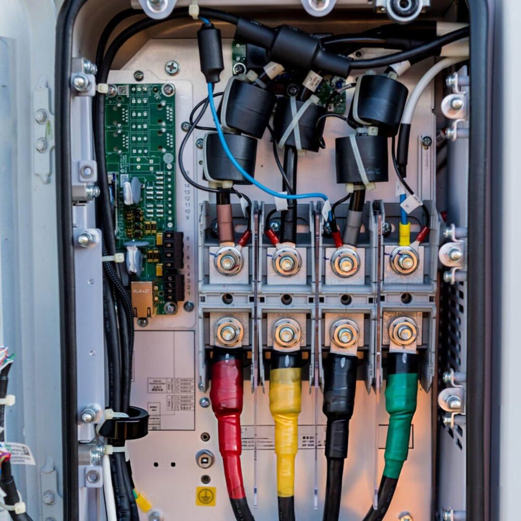
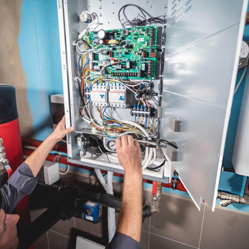
The five board images show application categories for comparison; they are reference images, not a catalog of prequalified XCC designs. Inverter and solar inverter requests need the conversion stage and grid or load boundary identified. A general power board may be a distribution or conversion assembly. A wireless charger must be assessed with the coil and receiver position. An energy storage board needs an explicit battery and system interface. Tell us which function you want built, and whether the delivery is a PCB assembly, power module or complete product.
OEM / ODM scope
Build-to-print or product development
Board to assembly
Define the supply level for each project
Sample to production
Agree approval and release requirements
Certifications available
Request documents for the applicable site and scope
01 / ENGINEERING FOCUS
Power Supply Control PCB in a complete product
Power boards need more than a nominal voltage. The useful project inputs include input range, output behavior, load profile, conversion or charging function, thermal envelope, protection requirements and the interface to the rest of the product.
02 / ENGINEERING FOCUS
Select the right power electronics scope
Power control projects are often quoted under the same short name even though they require very different hardware. In an inverter, identify the DC source, power stage, control board and output load. In solar conversion, add the photovoltaic input conditions and relationship to the installation system.
Electrical and thermal architecture
Define continuous and peak power, voltage and current ranges, duty cycle, conversion modes and the worst-case operating environment.
Protection and interface behavior
Describe the expected response to overcurrent, abnormal input, overheating, communication loss and recovery after a fault.
What to deliver
The commissioned scope can be a bare PCB, assembled control board, populated power stage, integrated module or finished product.
03 / ENGINEERING FOCUS
Engineering and integration decisions
XCC Technology can review the requested power board against the complete electrical system before defining engineering or build work. The project scope identifies interfaces, sample objectives, test limits and approval points. Production then follows a released board and test method rather than an assumed specification attached to a broad product name.
Electrical envelope: provide input and output ranges, peak and continuous loads, operating modes and the response expected during abnormal conditions.
Power stages and control: distinguish high-current conversion, low-voltage control, sensing, communication and charging functions; identify which are on the requested board.
Thermal and mechanical design: define available cooling, enclosure space, mounting, wiring and connector access.
Safety and market requirements: list the product-level requirements your team has identified and agree which party owns external assessment.
FROM SAMPLE TO SUPPLY
What your team can review before ordering
Scope, quotation and production handoff
A useful quotation separates engineering work, PCB assembly, specified components, magnetics or coils, cabling, enclosure and any external assessment. Provide continuous and peak power, input and output limits, duty cycle, cooling conditions, insulation or spacing requirements already defined by your engineering team, and the quantity forecast.
Quality and compliance evidence
Purchasing may need applicable quality management certificates, material declarations, component traceability, test records and a statement of the manufacturing site. Identify those documents during supplier qualification so the quotation and shipment package include the right evidence.
Build confidence before scaling production
A prototype should answer technical questions with a defined setup: operating points, switching or charging behaviour, thermal measurements and fault response. A pre-production build then checks manufacturability, test access, programming, assembly sequence and the availability of approved components.
What purchasing should compare between quotes
The exact board or system boundary and the rated conditions covered by the quotation.
One-time engineering, tooling and fixture costs versus repeat-unit pricing.
Customer-nominated versus supplier-sourced critical components and permitted substitutes.
Sample quantity, test coverage, records, external certification work and shipment scope.
What to send for a useful project discussion
System diagram and role of each requested board
Input/output and load profile
Battery, coil, solar or charger interface information as applicable
Enclosure, cooling and installation conditions
BEFORE YOU REQUEST A QUOTE
Frequently asked questions
Useful answers for engineering, sourcing and supplier qualification teams.
The five names describe different functions and operating conditions. A product may combine functions, but the actual partition of boards, controls and power stages must follow its system specification.
Share the source, load, operating modes, electrical interfaces, cooling arrangement and the part of the system you want built. A nominal voltage alone is not enough.
No. Product-level safety, installation and market requirements require their own scope and evidence. A board image illustrates a category, not approval.
Yes. Define the electrical boundary, interface signals, fault ownership and test points. The quote can cover the control assembly without assuming responsibility for an unreviewed external power stage.
The approved BOM, long-lead power parts, custom magnetics or coils, PCB construction, test fixtures, required evaluations and quantity all affect the plan. Share the forecast and approved alternatives to make the quotation usable for purchasing.
An open-board sample can answer some electrical questions, but heat removal, insulation, wiring and access may change in the finished housing. Define which results are provisional and what must be repeated in the final configuration.
Reference the approved hardware and firmware revisions, BOM, assembly and test instructions, acceptance limits, packing specification and any agreed traceability or inspection reports. Changes should be reviewed before the new build is released.
NEXT STEP
Discuss the next build
Tell us whether you need a board assembly, an integrated subassembly or a finished electronic product. Include the intended application, current design stage, expected quantities and the decision you need to make next. For the wider use environment, see Power Management; for the overall collaboration model, see OEM/ODM.