
OEM / ODM · PRODUCT SOLUTIONS
Automotive Electronics PCB
Define the electronics, qualification path and supply scope for your automotive project.
Automotive-related boards are not one common specification. A control board inside a vehicle, a motor-control subassembly and an EV charging unit can have different electrical environments, owners of product validation and market requirements. The first task is to identify the actual installation and XCC’s requested role.
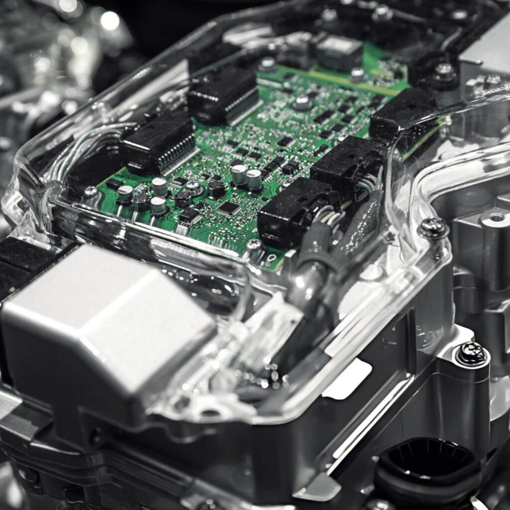
Product reference · OEM / ODM configuration
PRODUCT RANGE · 9 EXAMPLES
Automotive Electronics PCB Product Examples
Browse product boards and subassemblies from the existing page catalogue. Product images are category references; the approved drawing, BOM, configuration and acceptance criteria define each customer build.
01 / PRODUCT FAMILY
Motor Control PCB
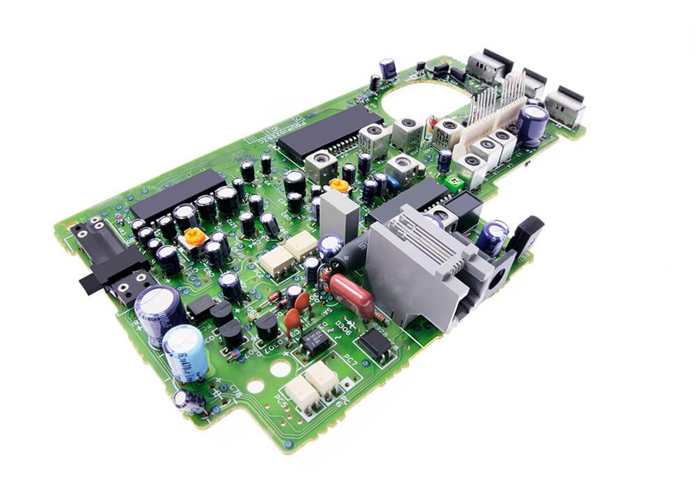
A motor control board manages the interface between a motor, its supply and the control system. Inputs include motor type, load behavior, feedback signals, duty cycle, switching environment and physical mounting. The same board category can serve industrial machinery as well as vehicle-related equipment, so the intended context belongs in the enquiry.
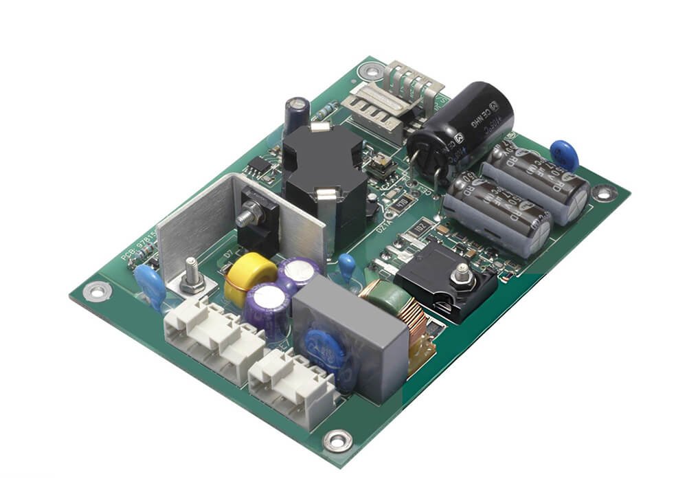
Motor Control PCB
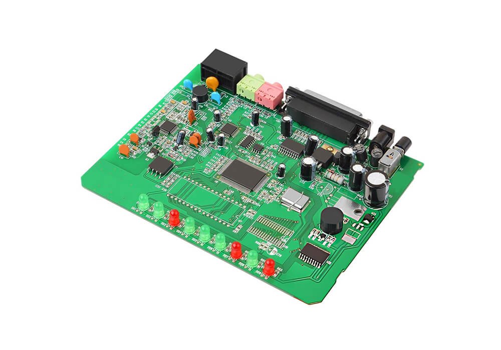
Motor Control PCB — Power Stage
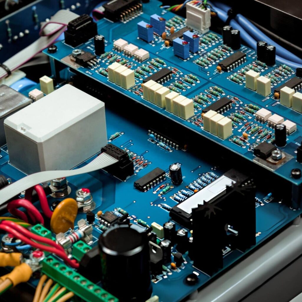
Motor Control PCB — Control Method
02 / PRODUCT FAMILY
EV Charger PCB
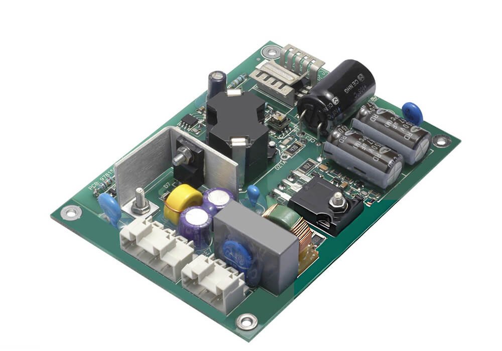
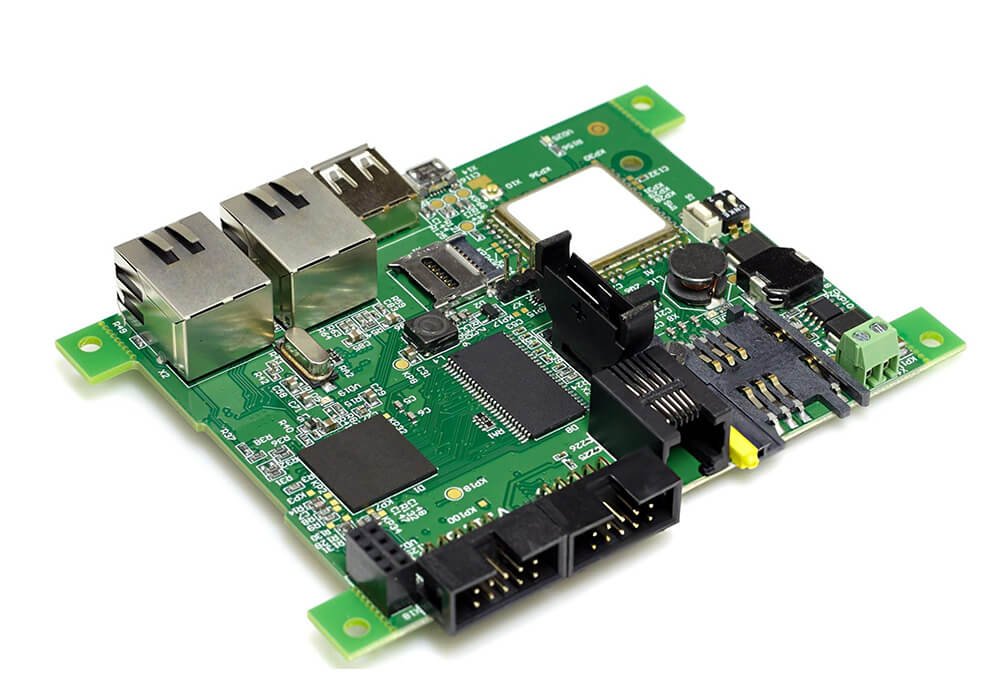
A charger board may handle control, communication, monitoring or parts of the power path in electric-vehicle charging equipment. State whether the request concerns a board, a charger subsystem or a complete unit, then provide electrical interfaces, installation conditions and target market. Product-level safety and charging requirements need their own agreed scope.
EV Charger PCB
EV Charger PCB — Charging Power
Smart EVSE Control PCB
03 / PRODUCT FAMILY
Automotive PCB
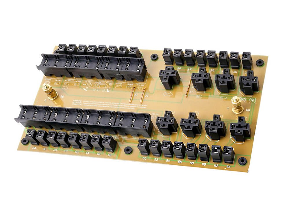
An automotive PCB is a broad category rather than a single construction. Explain the unit’s function, installation location, electrical environment, operating life and acceptance requirements. The manufacturing plan can then address the appropriate materials, assembly information, inspection and test records without assuming a certification from the application name.
Automotive PCB
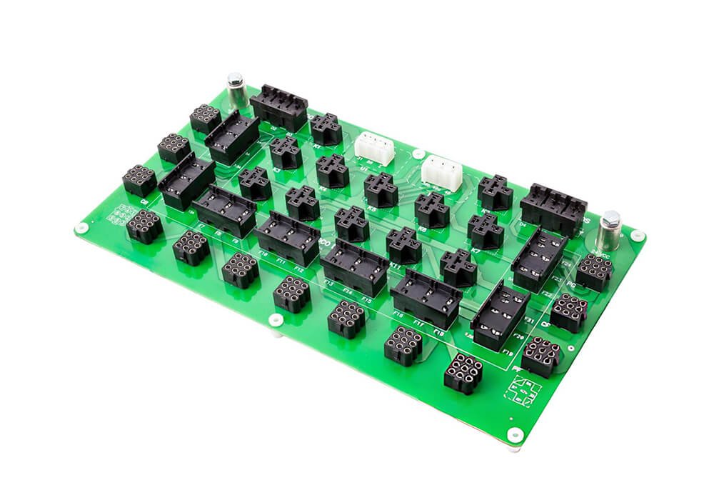
Battery Management Systems PCB
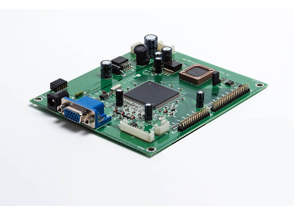
Engine Control Unit PCB
The Motor Control PCB reference shows a control function that may be used in vehicles or other machines. The EV Charger PCB reference concerns charging equipment, which may be installed outside a vehicle. The Automotive PCB reference represents an in-vehicle assembly category. These images illustrate board categories. State the actual installation, customer specification and required supplier tier when selecting a route.
OEM / ODM scope
Build-to-print or product development
Board to assembly
Define the supply level for each project
Sample to production
Agree approval and release requirements
Certifications available
Request documents for the applicable site and scope
01 / ENGINEERING FOCUS
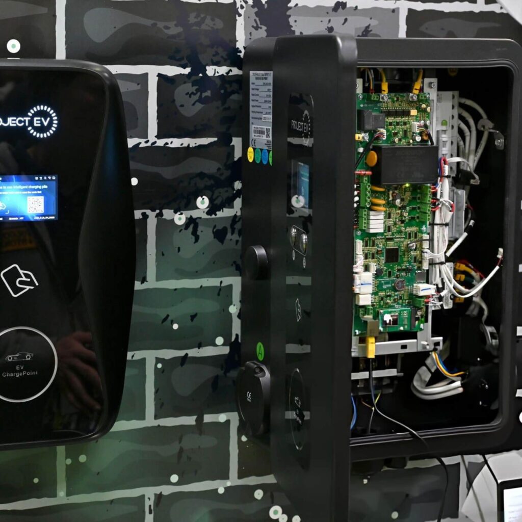
Automotive Electronics PCB in a complete product
Automotive-related projects need a precise description of where an electronic unit will be installed, what it connects to and who is responsible for vehicle-level validation. Board and assembly requirements vary between in-vehicle electronics, charging equipment and supporting infrastructure.
02 / ENGINEERING FOCUS
Choose the correct automotive project lane
The same buyer may need an in-vehicle controller, a motor-drive board and charging infrastructure. These are distinct programs. An in-vehicle unit must be defined against its vehicle location, electrical network, lifetime and customer acceptance process. A motor-control board must account for the actual motor, feedback and load.
In-vehicle electronics
Describe the module’s function, power supply, connectors, communication bus, thermal location and any failure response required by the customer.
Motor and charging electronics
For motor control, specify motor type, continuous and transient loads, sensing, duty cycle and what happens under stall or loss of feedback.
Delivery model
Your project may require engineering samples, build-to-print PCBA, an integrated subsystem or a finished product.
03 / ENGINEERING FOCUS
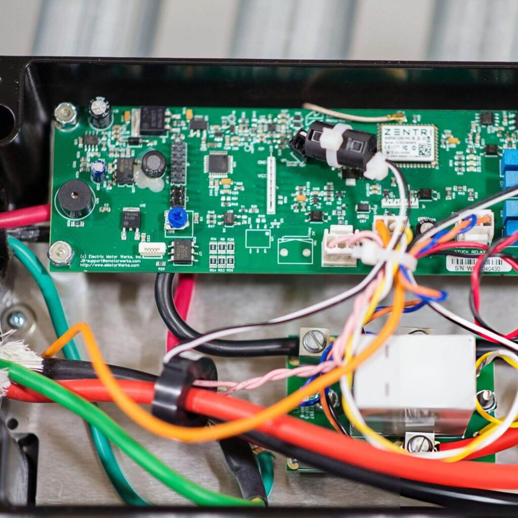
Engineering and integration decisions
XCC Technology can review a proposed vehicle or charger assembly against its customer specification and the requested supply role. The project scope defines sample builds, qualification evidence, change approvals and production checks before a repeat-order commitment.
Installation and interfaces: specify vehicle or equipment location, supply transients, communication links, connectors and mounting.
Motor control: describe motor type, load, feedback, duty cycle, switching behavior and fault response where relevant.
Charging equipment: distinguish control and monitoring boards from high-power stages and the finished charger.
Documentation: identify revision control, traceability, inspection and customer-specific requirements before quoting.
FROM SAMPLE TO SUPPLY
What your team can review before ordering
Qualification and change control buyers need to see
For a vehicle program, send the customer drawing or specification, critical characteristics, approved parts rules, required test methods, traceability depth and any supplier quality manual. The review should identify whether the requested deliverable is a prototype, production PCBA, charger subsystem or finished product.
Certificates and evidence for supplier approval
Automotive buyers may request an IATF 16949 or ISO 9001 certificate, scope and site details, along with material declarations, inspection results and program-specific records. An EV charger project may need different product and market approvals from an in-vehicle unit.
From engineering sample to controlled supply
An engineering sample should establish the specified electrical behavior, interface compatibility and major thermal or mechanical risks. A pre-production build should prove that the approved parts, programming, assembly instructions and test stations can produce the same configuration consistently.
What belongs in the commercial offer
- Product and installation description, customer specification and destination markets.
- Prototype or annual quantity, delivery schedule and expected program life.
- Responsibility for design, validation, external testing, tooling and fixtures.
- Nominated parts, sourcing restrictions, long-lead materials and approved alternates.
What to send for a useful project discussion
- Product and installation description
- Electrical and communication interfaces
- Motor or charger subsystem requirements if applicable
- Environment, life and test requirements
BEFORE YOU REQUEST A QUOTE
Frequently asked questions
Useful answers for engineering, sourcing and supplier qualification teams.
Does an automotive PCB image imply an automotive certification?
No. A board type or image does not establish a certification. Supplier qualifications and product requirements must be reviewed for the actual project.
Is an EV charger board the same as an in-vehicle board?
No. Charging equipment and in-vehicle electronics can have different installation, safety, communication and validation boundaries. Define the requested board and finished product separately.
Can a motor-control PCB also be industrial?
Yes. Motor control is a function used in many settings. State the target equipment and operating conditions so the correct requirements are applied.
What should an automotive RFQ include beyond Gerbers and a BOM?
Include the installation, customer specification, drawings, forecast, critical characteristics, validation ownership, traceability requirements and required supplier certificates. Those items determine whether the requested production scope can be quoted responsibly.
How are part changes handled after sample approval?
Define notification and approval rules before release. Review the proposed change against electrical performance, fit, test coverage and any prior qualification before a revised build is accepted.
Does an EV charger need the same qualification as an in-vehicle PCB?
No. Charging equipment and in-vehicle modules have different installation and product requirements. Define the complete product, target market, customer standards and responsible approval party for each program.
Can we supply a released vehicle PCB design for build-to-print?
Yes, start with the controlled design package, approved BOM, assembly instructions, firmware, customer specifications and test limits. The transfer review should identify gaps and agree sample approval before production supply.
NEXT STEP
Discuss the next build
Tell us whether you need a board assembly, an integrated subassembly or a finished electronic product. Include the intended application, current design stage, expected quantities and the decision you need to make next. For the wider use environment, see Automotive Electronics; for the overall collaboration model, see OEM/ODM.