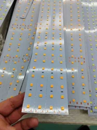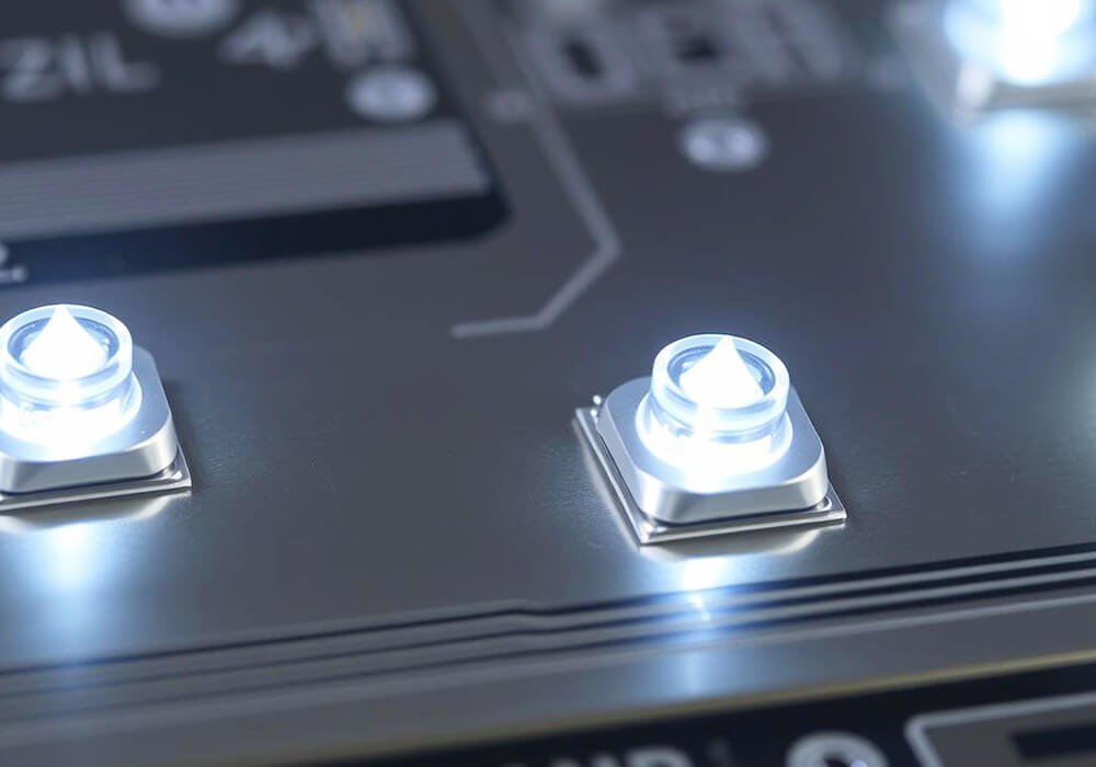
Lighting electronics that fit the complete system.
A lighting product must connect electrical performance with the light users see. The driver, light source, controls and enclosure all influence startup, dimming, heat and operation in the installed product.
Discuss your lighting electronics OEM/ODM requirements with XCC Technology. Start with the lighting task and identify whether you need support for the driver, control electronics, a subassembly or the finished product.
Define what the lighting product includes
A lighting brief should show the relationship between the supply, driver, light source and control inputs. It should also identify which elements already exist and which need development or manufacturing support.
Your project may concern a dimming controller, electronics integrated into a luminaire or a driver intended for a specified load. The brief connects that product with its supply, light source, control method and installation requirements.
Include the intended installation: an enclosed fixture, a cabinet, a surface-mounted unit or another defined location. Access for connections and service, the available space and the expected environment affect the electronics and assembly scope.
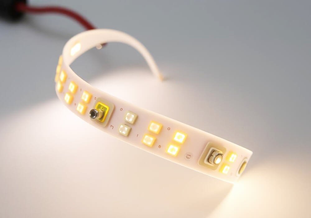
Engineering and manufacturing support for lighting electronics
Driver and control integration
We organize the requested electronics work around the selected light source, supply and control method. The development scope can address the driver or control circuitry, embedded behavior and the interfaces between them. An existing driver or controller is reviewed against the required operating conditions before a replacement or customization is defined.
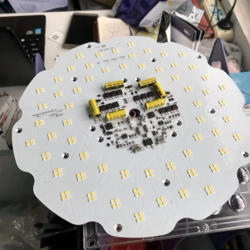
The objective is a product whose electrical response and visible lighting behavior can be evaluated together. The requirements identify the range, transitions and operating states to check, while the design scope identifies the parts we develop and the light-source or system information supplied by your team.
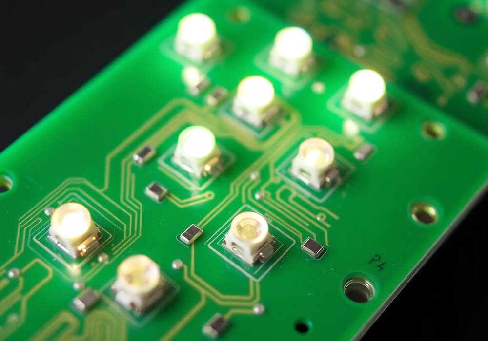
Mechanical and thermal coordination
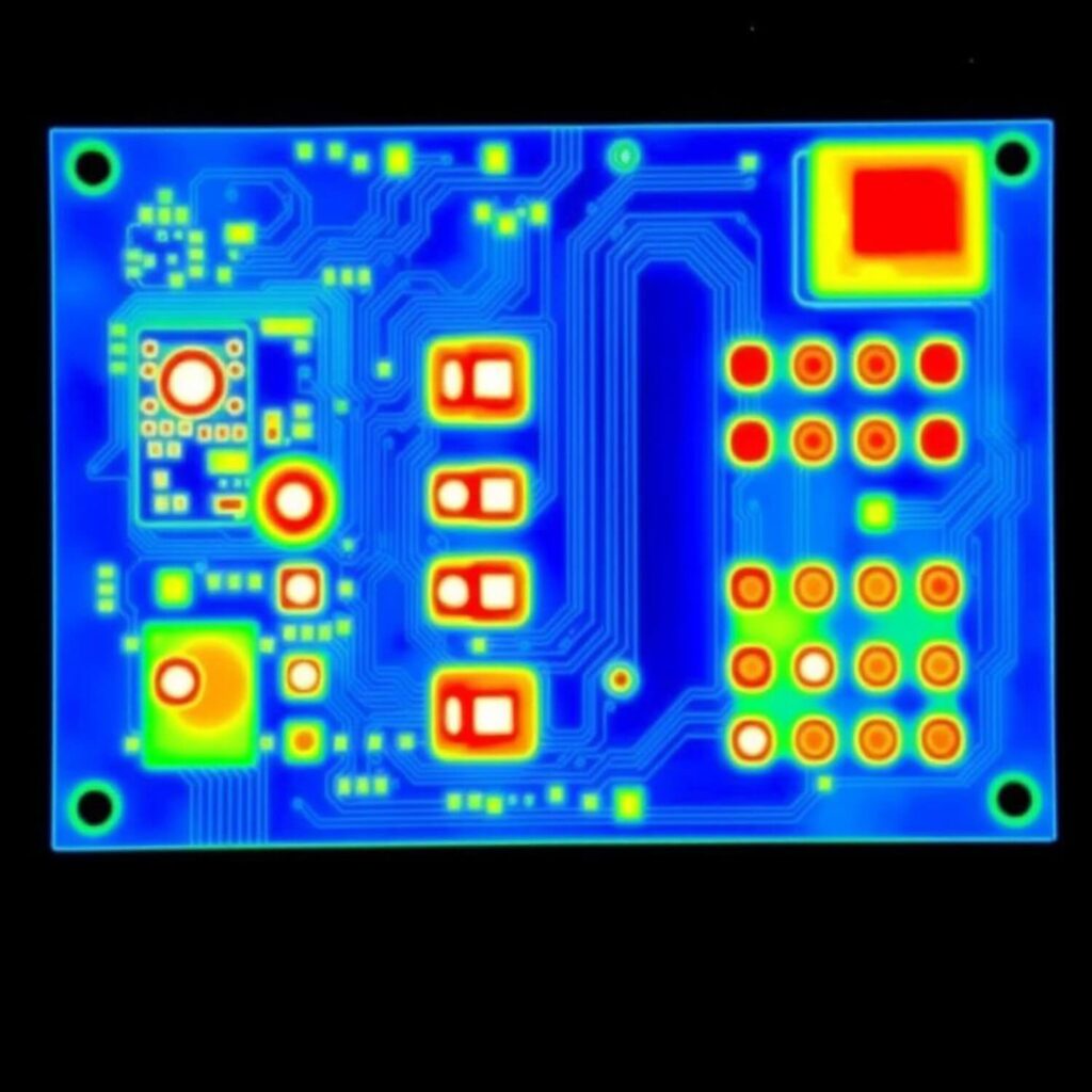
Lighting electronics must fit the fixture or housing and its installation. We coordinate board dimensions, connectors, mounting and the thermal arrangement included in the project with the mechanical design information. An evaluation assembly gives the teams a way to review fit, wiring and operation in the intended enclosure.
If the project requires optical measurements, environmental evaluation or market approval work, the responsible party and test arrangement are identified alongside the electronics scope. This keeps the engineering outputs and the complete lighting-product evaluation connected.
Production and handover
For manufacturing, the approved release identifies the electronics, wiring, configuration and specified light-source variant. Assembly instructions and functional checks are prepared around that configuration. Finished-unit requirements include the mounting parts, labels and packaging commissioned for the order.
The handover can include evaluation units, commissioned design information, an approved material and variant list, control settings where applicable, assembly details and the agreed test information. Those outputs help purchasing distinguish the unit being quoted and help engineering identify the version being evaluated.

Specify the behavior that matters
Light source and electrical load
Provide the light-source specification and its required operating range. Identify whether the system needs controlled current or voltage, how the load is connected and whether there are multiple channels. A power rating alone does not describe the load conditions the electronics must handle.
If a driver or light source has already been selected, share its specifications and interface requirements. Changes to either can alter the design assumptions and the evaluation needed for the complete product.
Dimming and control
Describe how brightness is commanded and what the user should observe across the required range. Include startup level, transitions between settings, behavior near the lowest level and the result when a control signal is removed or interrupted.
If the product uses sensors, local controls or an external lighting system, identify their interfaces and responsibilities. A communication or dimming standard is a specific project requirement; compatibility must be reviewed for the implementation and cannot be inferred from the application name.
Heat in the installed assembly
The enclosure, mounting position, adjacent components and airflow influence operating temperature. Describe the expected ambient conditions and the installation that will be evaluated. Where a thermal interface or heat-dissipating structure is part of the design, its material and assembly requirements should be defined.
The electrical operating point and the installed thermal conditions need to be considered together. Measurements on an exposed board do not automatically represent the same electronics inside the finished fixture.
Power changes and abnormal conditions
Identify expected supply variations and the required behavior during startup, shutdown and interruptions. Specify relevant overload or fault conditions and the intended response. Protection functions, recovery behavior and the test method need agreed requirements.
Market requirements may also affect insulation, electromagnetic compatibility and other evaluation topics. Identify the applicable product category and destination market so testing and approval responsibilities can be established.
For projects centered on a power function beyond lighting, see Power Management.
Review the product as a lighting system
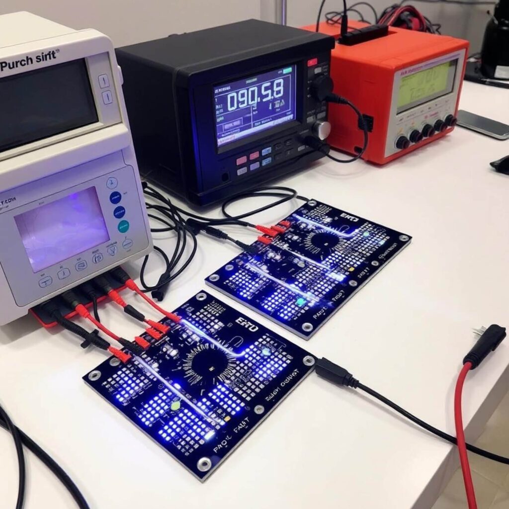
The evaluation plan should distinguish electrical checks from the lighting result. Electrical checks may assess supply behavior, output and control response under specified conditions. System evaluation may also consider visible dimming behavior, repeatability and operation in the intended enclosure.
Define which measurements are needed, their conditions and who supplies the equipment or external evaluation. Optical performance, lifetime, efficiency, ingress protection and compatibility claims require appropriate evidence for the actual product. They should not be inferred from a component specification or a generic application description.
When manufacturing is in scope, the accepted configuration should identify the electronics revision, light-source variant, software or settings where applicable, wiring and mechanical assembly. The production test must check the functions required to release that unit; broader qualification work has its own scope and records.
Choose the right project starting point
For a new lighting requirement, begin with the load and the desired behavior. For an existing design, provide its released documentation and explain the manufacturing support requested. For a replacement component or redesign, identify the existing installation, compatibility constraints and changes that need evaluation.
The agreed scope should state the delivery level and the roles of the customer, XCC Technology and any other contributors. Tooling, enclosure work, optical elements, external testing and market approval are included only when specifically agreed.
Information to prepare
- Light-source or load specifications, including channel arrangement.
- Supply requirements, output requirements and operating conditions.
- Dimming behavior and control interfaces.
- Installation drawings, available space and thermal constraints.
- Existing driver, enclosure or system specifications that must remain compatible.
- Target market, relevant approval requirements and the planned evaluation method.
- Current design status, intended assembly level, quantities and target milestones.
Lighting project questions
Can the enquiry cover only control electronics?
Yes. Describe the light source, driver and interfaces the controller must work with. Identify which parts are supplied by you and what output is expected from the requested work. A defined boundary helps assess the controller without assuming that the whole lighting assembly is included.
Can a driver be replaced without changing the fixture?
The mechanical fit, electrical behavior, dimming response, wiring and thermal conditions all need review. A replacement with the same nominal rating may still behave differently. Share the current specification and the aspects that must remain compatible.
What is needed to discuss a dimming problem?
Describe the affected brightness range, supply and load, control method and conditions in which the issue occurs. If possible, identify whether it appears at startup, during a transition or in steady operation. Existing measurements and sample configurations help define the investigation.
Does production testing establish product lifetime?
Production testing checks specified functions or characteristics of manufactured units. A lifetime claim requires a separately defined basis and appropriate evidence. Identify any lifetime or reliability requirement so its evaluation and ownership can be agreed.
Tell us about the light, the load and the installation
Share what the product must do and which part of the system needs support. We can discuss the electronics, integration and evaluation work needed for the next stage.